|
Experiment 1
|
- Concept: In general, electrical signals have DC and AC components.
For example: Consider an electrical waveform x(t) = 1 + cos(t). This signal
has a DC (direct current) component of 1 and an AC (alternating current) component of cos(t).
- AC vs DC coupling: Referring to the aforementioned signal x(t), DC coupling will show both components, i.e. 1 + cos(t). AC coupling will only show the periodic or alternating component, i.e. cos(t).
- Trace Triggering: Use this option with AC signals. When the time and voltage axes are aligned to the center of the oscilloscope screen, the LEVEL knob will change the y-intercept of the waveform. Remember, the y-intercept measures voltage. What is the y-intercept of x(t) with AC coupling? Using DC coupling, what is the allowable range that can be attained with the LEVEL knob? (½ pt) The slope option changes how the oscilloscope draws the waveform. There are 2 settings: rising and falling. The rising option will change the slope at the y-intercept to a positive value. Similarly, the falling option causes the slope to go negative.
- Pulse Width: Same as Duty Cycle. If you want to sound like a grad student, use Duty Cycle. This term usually refers to periodic waveforms (e.g. square waves, sawtooth). The duty cycle is the ratio of the amount of time the waveform is high to the amount of time the waveform is low. This ratio is measured over a period.
- Differential Voltage Measuring: When measuring 2 or more signals using the oscilloscope, all signals must share a common ground. A circuit has one ground which is marked clearly on the circuit diagram. So, this ground should be used for measuring signals with the oscilloscope. However, you usually don't do this with the DMM (digital multimeter). Bottom line: The DMM is inherently a differential voltage measuring instrument; whereas, the oscilloscope is not. If this confuses you, don't worry about it for now. You'll understand it in forthcoming experiments.
|
|
Experiment 2
|
- Concept: The water analogy for electricity. This analogy has been used in many textbooks and it serves as a good starting point to understanding the mysteries of electricity. You can think of electrical current as the amount of water flowing through a pipe. There really is no good analogy for voltage; however, the term voltage replaced the verbose term, electromotive force, which was the term physicists used when they first observed the effects of electricity. So what forces move water? Ans: Gravity and Pressure. If you forced me to draw an analogy of voltage for water, I would say you could think of voltage as the effect of gravity and pressure on the water molecules acting over an infinitesimal distance. That's a bit abstract, so let's get back to more concrete examples of this water analogy.
Whenever there's a transfer of water from one point to another, you will have current or water flow, e.g. pouring water out of a bucket. Using this analogy, electrical current will flow when there's a voltage difference between two nodes. Resistance can be thought as how clogged or wide the pipe is in which the water is flowing through. If you want more electrical current, you would want a bigger and more conductive wire, so that the resistance is lower. We can carry this analogy to energy and power, but you'll learn this in the next lab. Can you think of the correct analogy of energy using the water analogy? (½ pt)
- Measuring Voltage & Current: Many students have problems measuring current than voltage. Many students blow a couple of fuses before actually mastering the art of measuring current. Using the water analogy, think about how you would measure the water flow through a pipe. You would need to insert a probe into the pipe that would not impede the water flow so you can get an accurate measurement. Hence, to measure electrical current, you break the circuit at a certain point and insert the ammeter. Consequently, the ammeter is now part of the circuit. It's important to realize that a good ammeter will have a very low resistance. Can you explain why? (½ pt)
|
|
Experiment 3
|
- 1st Motor Concept: This is the first electromechanical device introduced in this lab course. For those of you that remember their first year of physics, Faraday's Law is at work here. This law describes the initimate relation between electric fields and magnetic fields. More specially, a change in the electric field also changes the magnetic field and vice versa. We can exploit this effect by using the magnetic force to give rise to motion. This simple principle is behind all electromagnetic devices such as motors, relays, alternators in automobiles, etc. More specifically, an electric motor changes electric energy to magnetic energy to kinetic energy; whereas, a generator does the opposite. You should have this effect when you spun the axis of your motor and measured a small current. Hydroelectric plants do the same thing but at a much grander scale.
- 2nd Motor Concept: Because a motor is an electromechanical device it will have an inductance. Can you identify what parts of the motor contribute to the inductance? (½ pt) Here, there's no appropriate water analogy for inductance. Inductance is the effect of charged particles, electrons, interacting in such a way to give rise to a magnetic field. One way to do this is to coil up a wire so it resembles a slinky. Hence, the electrical symbol for an inductor looks like a coiled piece of wire. After completing this lab, you should have observed that the voltage and current through the motor have AC characteristics or small ripples. Due to the inductance in the motor, voltage 'leads' the current by 90 degrees. This can be seen mathematically by the formula, V = L di/dt.
- 3rd Motor Concept: Since an electromechanical device converts electrical energy to mechanical energy, it is necessary to relate some of the basic definitions in both electricity and mechanics. One, probably most important, relationship is the current is directly proportionally to the torque generated by the motor. Using the basic properties of inductance, can you figure out a way to increase the torque you built in lab? (½ pt)
- Power Characteristics of Electric Motors: You should have observed the power versus voltage graph for your electric motor has an isolated peak then drops and rises again. This isolated peak occurs because it takes more power and more energy to move an object at rest than to move an object that is in motion. Once the motor overcomes the static frictional and gravitational forces and starts moving, it take less energy to keep it moving. Also, another observation that you should have seen is the efficiency of electric motors (under no load) is in the range of 90% and above. This is one of the biggest appeals is to incorporate electric motors into commercial automobiles. Why haven't electric vehicles (EVs) taken over the automobile market yet? Hint: think about power. (½ - 1 pt)
|
|
Experiment 4
|
- I-V Characteristics of Nonlinear Devices: In the previous lab, most of the devices, such as the motor and lamp, were nonlinear because the I-V curves were not linear for a full range of voltages. Hence, Ohm's law doens't hold for all voltages, but does hold at individual data points. In this lab, you should have seen that the diode, Zener diode, LED, and transistor are nonlinear devices. Based on these I-V curves these devices, there are many models to relate the current and voltage through these devices. Some of the models involve exponentials (e.g. the diode), parabolas, and lines. Note, that most models use a combination of these models for the different states these nonlinear devices can take on, such as the transistor and its states are cutoff, saturation, linear, and reverse cutoff (Note: lecture may use different terms). To get accurate models for these nonlinear devices, you must look at the device physics (for those of you that are interested in this area of electrical engineering).
- Uses of Transistors: One of most revolutionizing inventions in electrical engineering is the transistor. It is found is also every electrical device you can think of. Before transistors were incorporated into electronic devices, many of them use vacuum tubes and electromechanical devices to perform logic operations. These machines were extremely huge, bulky and could not be easily carried from place to place. The earliest computers were as big as high school gymnasiums and were so loud that to repair them one had to wear earplugs. During this era, one of these mammoth computers stopped working. After searching for the faulty component, the workers found a moth caught in between on the electromechanical devices. From that day, a bug is referred to a computer crashing. Fortunately, modern day computers don't have these type of "bugs" anymore.
- Uses of Diodes: One interesting use for the diodes are solar cells. Solar cells conduct current when they are subjected to light. The intensity of the incident light directly proportionally to the current generated by solar cells. Also, more current is generated when the light shines perpendicular to the surface of the cells. We can view solar cells as small power supplies. Remember, when a diode turns on, it appears like a small voltage source. Combining these solar cells in series/parallel combinations, different power settings can be obtained. A certain manufacturer's solar cells can generate 0.5 DC Amps at 2 DC Volts. Your stereo needs at least 12 Watts at 1 Amp. How would you configure these solar cells to supply enough power to run your stereo? (½ pt)
- Uses of Voltage Regulators: These can be thought as DC-to-DC converters. These are also found in many electrical devices such as your vehicle in lab, commerical automobiles, and portable devices such as cell phones, pagers, etc. Specifically, in this lab, you will be using logic gates that run on 5 Volts. But your battery voltage is at 10 to 11 Volts. To bring this voltage down to 5 Volts, the car has voltage regulator built into it. These devices are quite efficient in terms of power. A certain company has a 12 Volt to 5 Volt DC-to-DC converter with a power efficiency of 95%. If the maximum recommended input power is 12 Watts, what is maximum value of the current at the output of the voltage regulator? (½ pt)
- Comments about the Voltage Regulator circuit: It seemed that a lot of people did not understand the voltage regulator circuit. The following circuit shows the same circuit presented in lab except the diodes are replaced by their equivalent voltage drops. In lab, you found that the voltage drop for the diode, 1N5406, was around 0.7 V. For the breakdown voltage of the Zener diode, 1N4734, the value was around 5.6 V (refer to spec sheet in lab manual appendix). Hence, we can draw the equivalent circuit with the diodes replaced by the appropriate voltage drops. Note the polarity of the voltages for each diode, especially the Zener diode. Think about why the polarity appears the way it's drawn on the circuit.
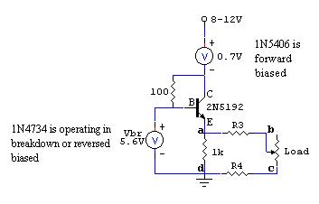
The NPN transistor, 2N5192, is operating in saturation (closed switch). To operate in saturation, the voltage between the base and emitter (Vbe) is around 0.7 V, same as the forward bias voltage of a diode. Hence, by KVL, Vad should be around 5.6 - 0.7 = 4.9 V. Since the wires between points a & b and c & d have a small resistance, the voltage Vbc will be less than Vad. By KVL, Vad = Vab + Vbc + Vcd. Clearly, one would want to minimize the adverse effects of the resistance introduced by the wires. The general idea of this circuit is that the 1 kOhm provides feedback such that the voltage across it stays around 4.9 V. You'll learn later that this is how to provide negative feedback in transistor circuits. We start losing 4.9 V if the load becomes too low. More specifically, if the equivalent resistance of the load and 1 kOhm is 1 Ohm, then 5 Amps is needed to maintain 5 Volts across Vad. This is not possible since the maximum current output from the power supply is 1 Amp. Hence, voltage regulation is lost. Therefore, larger loads are better so that Vbc stays in an acceptable range. If we were to replace the load with TTL (transistor-transistor logic), we would expect the input resistance of such logic gates would be very large. This will be covered in Experiment 6.
|
|
Experiment 5
|
- A brief lesson about transistors: In this lab, you learned that transistors can act as current amplifers. Before explaining how the current amplifier works for your car, you will need a brief background on the concepts of transistors. If you look at the word "transistor", it's composed of two words: "trans" and "resistor". Hence, the word "transistor" represents a device that can change its resistance under certain conditions. The difference between the transistor and the variable resistor is you can change the resistance between two points (collector and emitter for bipolar junction transistors, BJT, or drain and source for metal oxide semiconductor field effect transistor, MOSFET) by changing the current going into the base (for BJT) or the voltage across the gate to source (for MOSFET). In other words, we change the resistance of the transistor electronically, either by current or voltage. Usually, this current or voltage is really small. Consequently, to have a high current gain, the transistor should have a low turn-on resistance and low input current. So a transistor can be used as a current amplifier or a switch.
Consider the following two circuits. In lab, you saw that the motor can be placed at either the collector or emitter of the NPN transistor. We can do the same for MOSFETs. We use different terminology for the three terminals of the NMOSFET: G = gate, D = drain, S = source. Instead of using a motor, an automotive LED is used. It is placed at the drain (D) in Circuit A and placed at the source (S) in Circuit B. To turn on the NMOSFET, the voltage across gate to source (Vgs) must exceed 4 Volts. Consequently, when the NMOSFET turns on, it looks like a very small resistance between the drain and source, Rds = 0.54 Ohms.
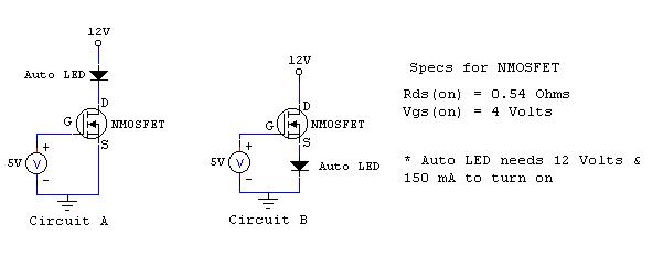
Note, Circuit A and B are using the transistor as switch to control when the automotive LED turns on and off. Which circuit will correctly turn on the LED? Circuit A? B? both A & B? neither A nor B? Why? To receive full credit, you must explain how Circuit A and B work. (1 pt) This is a difficult problem. Hint: You should think about what happens to the voltage at the source of the NMOSFET.
|
|
Experiment 6
|
- Relating Voltage Levels to Logic Values: To relate a continuous range of voltages to discrete logic levels, we must somehow map 0-5 Volts in the analog world to 0 (false or LO) & 1 (true or HI) in the digital world. For TTL (transistor-transistor logic) circuits, we need to divide the 0-5 Volts into parts: one for logic LO, another for logic HI, and an indeterminate region where the logic level is not defined. The following is a summary of how we divide up the continuum of analog voltages into the discrete domain of logic values:
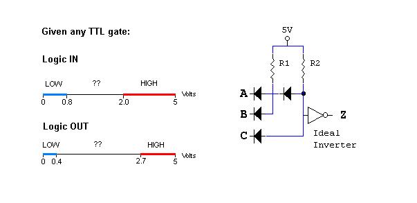 In this lab, you studied DTL gates. The above circuit is another DTL gate. What is the logic function? In other words, how does the output Z relate to the inputs A, B and C? (½ pt)
|
|
Experiment 7
|
- Sensors & Sensor Height: You're probably wondering how your car can detect the white tape. To do this task, we have provided IR (infrared) sensors. Each sensor has IR transmitter and receiver. If enough light is reflected back by a white surface to the receiver, then the sensor will output a logic HI, otherwise, the output is LO. Clearly, if the white surface is not close enough to the sensor, then you will not be able to reliably sense the white tape. Also, if the sensor is too close to any surface, then the sensor will detect a non-white surface as white or reflective. This lab will help you determine the "best" sensor height, so that you can get good and reliable logic levels from your sensors. You should know this height to the nearest millimeter. If you don't know this value, your car WILL NOT WORK PROPERLY.
- No extra credit for this experiment.
|
|
Experiment 8
|
- Car Algorithms: We present 2 algorithms of detecting the tape: follow the tape or hug the tape. The first circuit with the crossed sensors followed the tape. In other words, the inner sensors always had to have some part of the tape in the field of vision of the innermost sensors. For the second circuit, the sensors were uncrossed. This didn't follow the tape, but in fact hugged the tape if the inverters are removed. More specifically, when the tape came into the view of the inner sensors, the car will turn away from it. Hence, for this "hug the tape" algorithm, the innermost sensors must be separated by at more than width of the white tape. It's your decision to choose which one to use for the design challenge. Both are effective. Successful car designs have used either of these algorithms.
- For the design challenge, a car design that can successfully complete 3 consecutive right turns will usually get full marks on the final track. Show me a working circuit (with sensor placement & circuit diagram) that can reliably complete 3 consecutive right turns, stop at an obstacle, and obey all the design challenge rules by the end of experiment 11, you'll receive 2 points of extra credit.
Hints: Begin by improving 1 of the 2 circuits presented in Experiment 8. When designing the circuit for your car, you should start with a pen and paper and draw out a sensor placement & circuit diagram. Designing your circuit on paper will help you save time from mindless tinkering in lab. You should know the "best" sensor height to the nearest millimeter. You may use the logic gates included in the appendices in the lab manual. You may use the Current Amplifier Bridge (CAB) module. This allows the motors be ran forwards, backwards, and stop. Refer to my handout for improving the performance and reliability of your car for further information. Generally, it is not a good idea to hard-wire OR more than 3 sensors into one logic input. Use the KISS principle. Refer to handout on design challenge strategies for further circuit design considerations. Good luck!
|
|
Experiment 9
|
- Pulse Width Modulation: You may have heard of the term modulation such FM (frequency modulation) or AM (amplitude modulation). Both of these types of modulation change the value of the frequency or amplitude of the signal, respectively. So, pulse width modulation is a method to change the pulse width of a periodic waveform. One can also think of this as varying the duty cycle of the periodic waveform (remember experiment 1?) Pulse width modulation has its uses in more sophisticated methods of charging batteries, especially, alkaline.
- Controlling the speed of the motor: Controlling the speed of the motor is really controlling the duty cycle of the logic input going to the motor. For example, if the duty cycle of the input to your current amplifer was 50%, then your motor would run at 50% speed. In this lab, you saw how you can vary the pulse width using a comparator to compare the binary value of the counter to the binary value from the multiplexor. Hence, we could use either pin 5 or 7 to control the speed of the motors.
- Referring the block diagram on page 71, let A and B be the decimal representation of the number going into the comparator of channel A and B, respectively. Find the duty cycle of pin 5 AND 7 as a function of A only. In other words, the duty cycle = f(A)/T. What is the value of T? Hint: T should be a constant (½ pt)
|
|
Experiment 10
|
- Hugging the tape: This lab introduces the "hugging the tape" algorithm with speed control. Would this algorithm work without speed control? So it detects black instead of white. Whenever it detects white, the car will slow down. This algorithm best simulates how you would drive on the road. Typically, safe drivers slow down when they take turns. This lab will show this.
|
-->
|
Design Challenge Issues
|
If you can answer all the following questions, you should do well on the design challenge.
- What's the "best" sensor height?
- What's your final sensor placement?
- How are you approaching turns? Are you slowing down to take turns or going full speed and compensate for overshooting the turn?
- Can I complete 3 consecutive right turns reliably?
- What's my car algorithm/strategy? Hug or Follow or Remember the tape?
- How many speeds do I need? Do I want to go in reverse?
- Does my car get stuck on the track? How do I fix this?
|